Firmware / Hardware / Integration

From circuits
to working
systems.

I’m Anas. I design STM32 firmware with custom drivers, communication protocols, and fault-recovery logic, then bring it together with custom hardware.

Open for freelance projects ~20 hrs / week
DESIGNED DOWN TO THE DETAILS
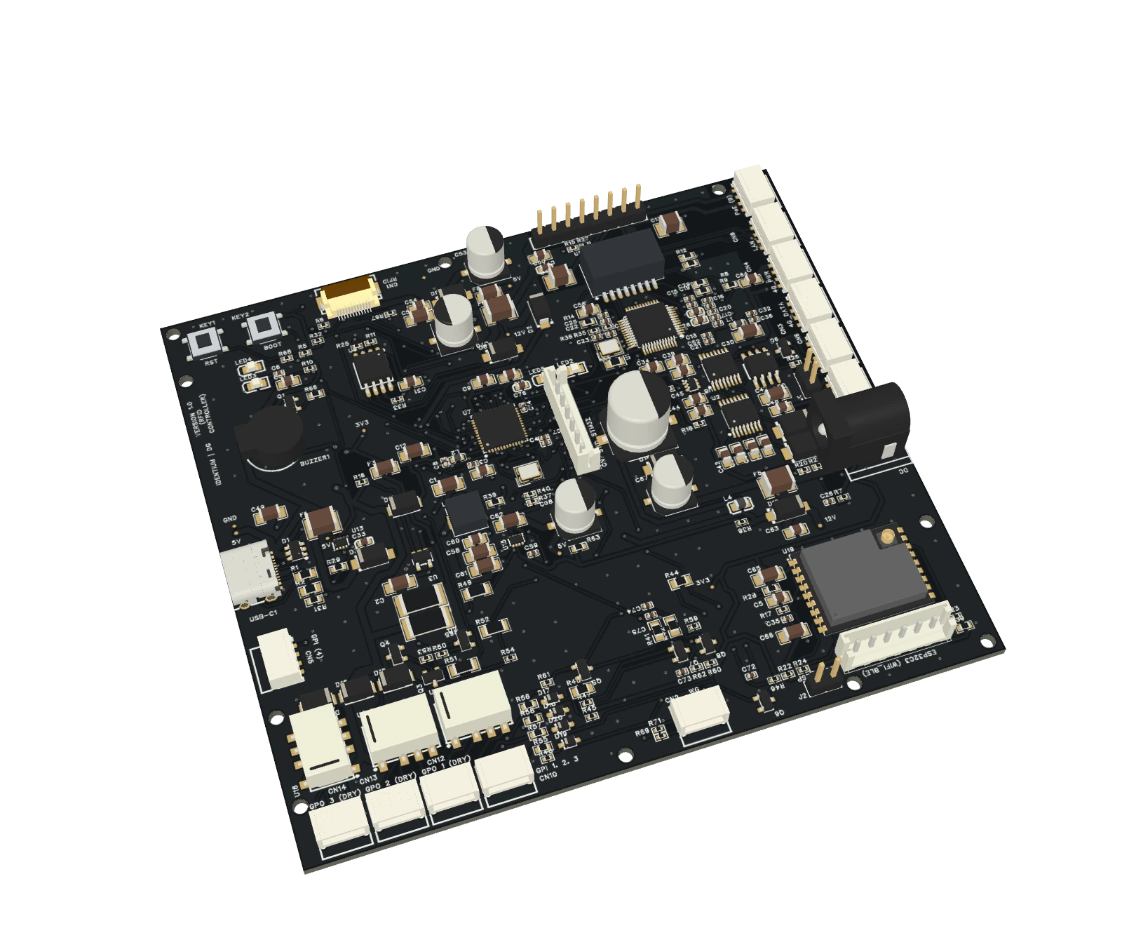
Populated black RFID controller PCB with STM32 controller, network connectors and power circuitry, shown as a 3D design visualization.
Custom RFID controllerSTM32F411 · Final PCB design3D preview
Hardware testing pending
FROM REGISTER TO SYSTEM
Embedded CSTM32Register-level driversCustom protocolsPCB designSystem integration

01 / Firmware engineering

Custom firmware.
From the registers up.

Designed for industrial RFID control: peripheral drivers, protocol handling, and recovery built into one connected system.

I designed the firmware architecture and custom drivers, coordinated the complete system, and carried out most of the hardware testing.

01

Control at the register level

Custom UART, SPI, I²C, GPIO and RCC drivers, plus a W5500 Ethernet driver. Peripheral state and interrupt handling stay visible and debuggable.

02

Protocols with a clear path

RFID framing and CRC checks, host-command parsing, TCP/HTTP flows, and a framed STM32–ESP32 link. Reader logic stays on the STM32.

03

Recovery designed into the system

Watchdog handling, startup stop/flush/retry, retained fault records, MPU stack protection, and loop timing for diagnosing failures on hardware.

04

Settings that survive a restart

Alternating internal-flash sectors, versioned records, sequence numbers, CRC32 checks, and settings migration between firmware revisions.

ARCHITECTURE OVERVIEW

One system.
Defined responsibilities.

Bare-metal C · Cooperative task loop

  1. 05
    ApplicationReader control · Inventory · Industrial I/O
  2. 04
    ServicesConnectivity · Settings · Diagnostics
  3. 03
    ProtocolsSilion frames · Host commands · TCP / HTTP
  4. 02
    Custom peripheral driversUART · SPI · I²C · GPIO · RCC · W5500
  5. 01
    Board supportSTM32F429 Discovery / STM32F411 custom

F429 bench platform · F411 build awaiting board tests.
ST HAL is used for clock, USB and flash integration.

DOCUMENTED HARDWARE CHECKPOINTS

Design decisions checked on the bench.

3/6 → 6/6Reset recovery after the startup fix
Faults capturedDeliberate usage, bus and stack faults recorded

02 / Selected work

The firmware.
The complete system.

The custom firmware connects the reader, the network, and the operator tools. Here’s what that looks like in practice.

02 — CUSTOM HARDWARE

Designed for the
next iteration.

A dedicated STM32F411 controller board, taking the system from development boards toward a compact, integrated design.

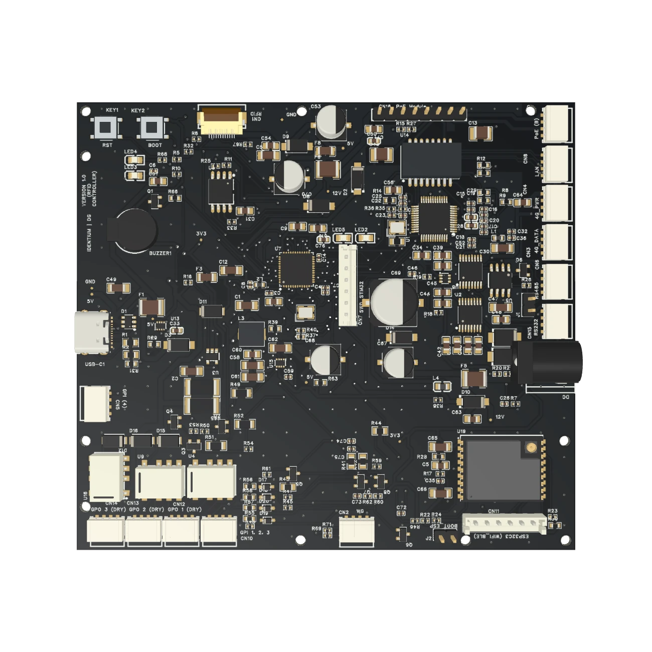
Top view of the populated custom controller PCB design.
FOOTPRINT109.49 × 98.32 mm
PLACEMENT PREVIEW223 components
CURRENT STAGE

Final Gerber revision.
Hardware validation ahead.

Black finish visualization using Gerbers and pick-and-place data.

03 / In action

See the system
come alive.

Screen recordings and a look at the actual bench setup. The software, the wiring, and the work in between.

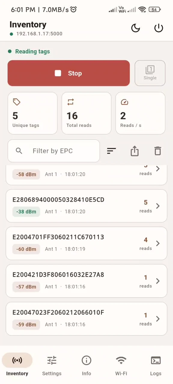
Short, silent excerpts from my project recordings. Bench footage uses development boards; the custom PCB has not been tested yet.

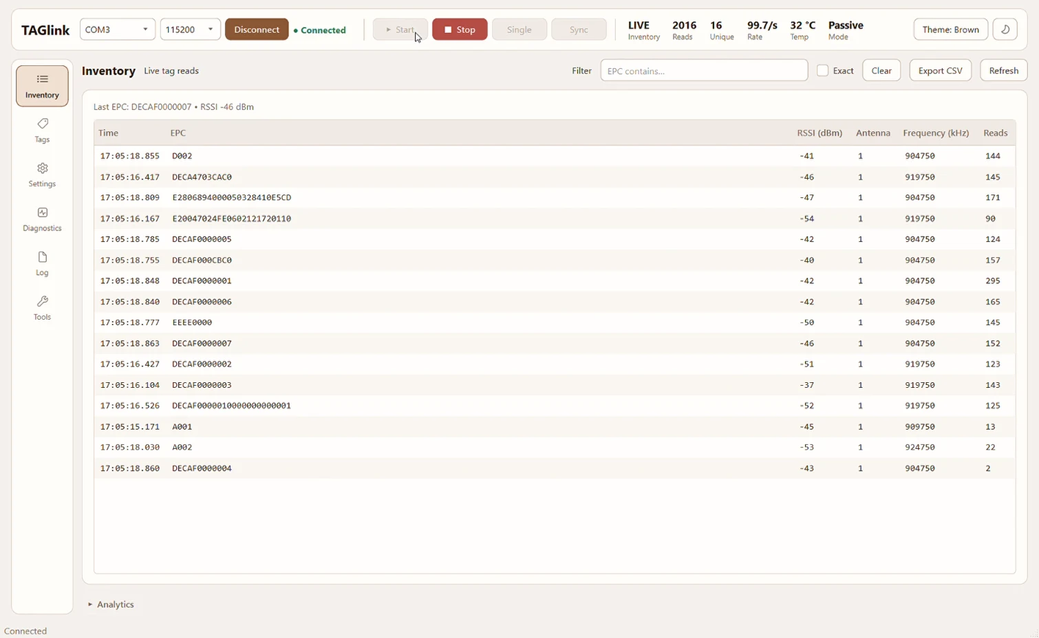
TAGlink Desktop · Live RFID inventory12 SEC / SILENT

04 / How I can help

Let’s build your
next working thing.

Focused freelance support for a specific technical challenge or a connected prototype.

01

Embedded
firmware

Bring up peripherals, integrate modules, and get devices talking reliably.

  • STM32 / Embedded C
  • UART · SPI · I²C · GPIO
  • Protocol integration
  • Debugging & recovery
↗
02

Schematic &
PCB design

Turn a hardware concept into a practical schematic and a board layout for your next prototype.

  • KiCad / EasyEDA
  • Component integration
  • Board layout
  • Gerbers & assembly files
↗
03

Tools &
integration

Make your device easier to operate, test, and diagnose with a purpose-built companion interface.

  • Python / PySide6
  • Flutter
  • Device control interfaces
  • Test utilities
↗

A clear scope, practical milestones, and testing that fits the hardware. Let’s start with what you need.

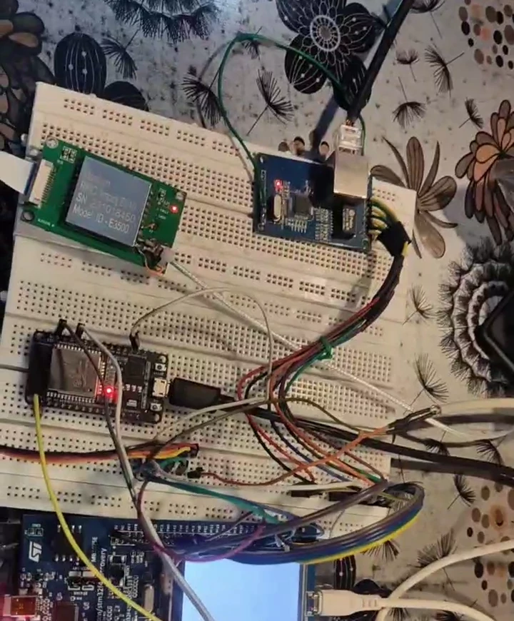
The real prototype: an STM32 development board, ESP32 module and RFID reader wired together on a breadboard. FROM MY WORKBENCH

05 / The person behind the board

Hi, I’m Anas.
I like making
things work.

I’m an embedded developer based in New Delhi. I work across firmware and electronics, with a particular interest in the details that connect the two.

For my RFID project, I designed the firmware, coordinated the hardware and software design, and carried out most of the bench testing. Datasheets, protocol traces, and real hardware guide how I build.

2021–2024

Electronics Engineering DiplomaJamia Millia Islamia

Jan–Jul 2026

Drone programming & assembly trainingEnord · ArduPilot, calibration & troubleshooting

More on GitHub

06 / Start a conversation

~20 hours / week

What are you
building next?

A new board, a tricky driver, or a device that needs to connect.
Tell me about your project, timeline, and where you need help.

Let’s talk about it
PROJECT NOTES / 01

Firmware · Integration · Bench testing

From bare metal
to connected RFID.

I designed the firmware and coordinated an STM32-based UHF RFID controller, bringing custom drivers, an external reader module, network connectivity, and operator tools into a working bench prototype.

The challenge

Keep reader commands, continuous tag data, saved configuration, and multiple host interfaces working together within a bare-metal application.

What I built

A layered system around a Silion/Impinj E310 RFID module, with distinct board support, driver, protocol, service, and application layers.

Three problems, three useful lessons

01

A stable Wi-Fi command path

Debugging an STM32 I²C interrupt loop and ESP32 task timing led to peripheral-state and reply-timing fixes. A documented F429/ESP32 bench checkpoint completed 1,000/1,000 commands with zero I²C errors, with a 31 ms median round trip.

02

Recovering while the reader is still streaming

An STM32 reset left the reader sending tags into initialization. Stopping inventory, flushing stale data and retrying configuration improved recovery from 3/6 to 6/6 resets in the recorded test.

03

Keeping uploads moving

Separating HTTP acknowledgements from commands and increasing batch sizes corrected the upload flow. A host simulation delivered 2,000/2,000 tags at 200 reads/s with a 400 ms round trip. Hardware testing later confirmed reception without a recorded throughput figure.

Where it stands

The recordings demonstrate the development-board prototype and both TAGlink interfaces. The custom STM32F411 PCB design is complete, with hardware testing still ahead. A STOP-command timeout near the end of the original mobile recording remains an item to investigate.

These are documented development checkpoints, not tests rerun for this website. The bench prototype and the untested custom PCB are separate stages of the project.

Have a similar challenge?
PROJECT NOTES / 02

Schematic · Board layout · Assembly data

A custom home
for the firmware.

The goal: bring the controller functions onto a dedicated board for the next hardware iteration.

Populated RFID controller design visualization.

Design and integration

I coordinated the overall hardware design alongside the firmware, bringing the STM32F411 controller, connectivity, power circuitry and external interfaces into a custom PCB layout.

The final EasyEDA Gerber revision defines a board approximately 109.49 × 98.32 mm. Its pick-and-place file supplies the component locations and rotations used for the populated 3D preview.

What the preview represents

The viewer combines the final Gerber geometry with 223 component placements and 10 copper test points. Black solder mask is a visualization choice. Components use library package models and simplified equivalents where exact models were unavailable; the preview is not a dimensional assembly check.

Current stage

The Gerbers are the final design revision supplied for this project. The custom board has not been hardware-tested. The working prototype shown elsewhere uses STM32 development boards and a breadboard setup.

The KiCad schematic material in the project archive represents another design variant. It is not presented as the exact schematic for this final EasyEDA board.

Explore the controller

Drag to rotate · Scroll to zoom · Use the view buttons for preset angles. View a still image ↗